Nessun prodotto
BLOG NEWS
 USARE UN DISPLAY LCD 16x2 CON LA IOT PROTO SHIELD PLUS
  Cosa ne pensa Paolo Aliverti della IoT Proto Shield Plus?
  USARE UN DISPLAY OLED SSD1306 128X64 CON LA IOT PROTO SHIELD PLUS
  USARE UN DISPLAY OLED SSD1306 128x64 CON LA IoT PROTO SHIELD PLUS
  Il Bus I2C sulla IoT Proto Shield Plus
 Search on blog
Follow us on facebook
I più venduti
-

Proto Shield Plus STARTER KIT
Questo kit è rivolto principalmente a chi desidera iniziare a...
69,90 € -

Proto Shield Plus LCD KIT
La scheda PROTO SHIELD PLUS rende comodo ed immediato sperimentare e...
56,00 € -

Adattatore da SMD a piastra sperimentale (confezione 10pz)
Adatta facilmente componenti SMD a piastra sperimentale (breadboard) con...
3,90 € -

Proto Shield Plus KIT BASE
La scheda PROTOSHIELD PLUS rende comodo ed immediato sperimentare e...
52,00 €
The Proto Shield Plus Board Layout
Published : 09/03/2018 10:45:38
Categories : Proto Shield Plus
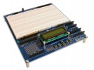
Lets take a look at the Proto Shield Plus board layout
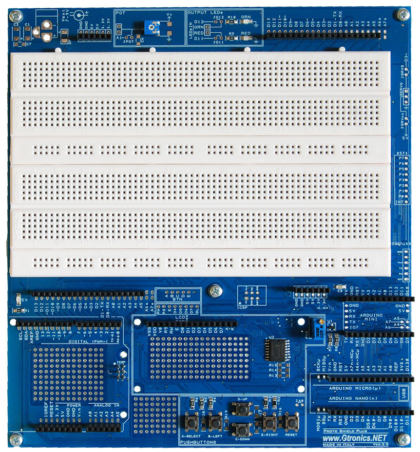
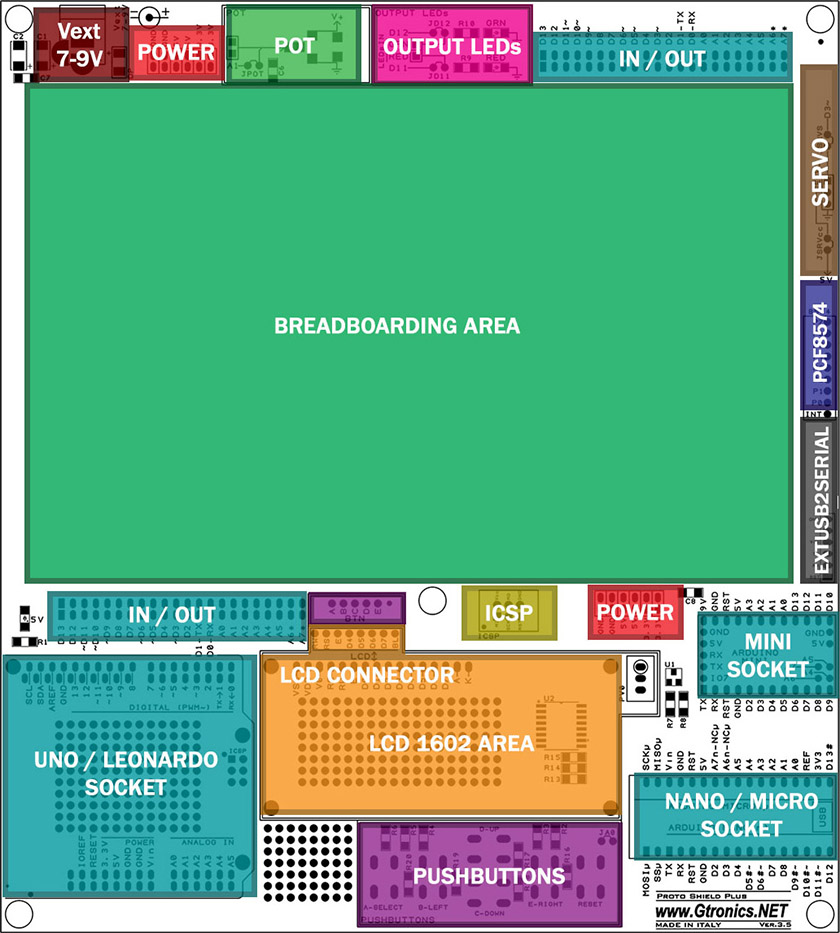
Proto Shield Plus TOP side
ARDUINO SOCKETS
The UNO / LEONARDO socket accepts UNO, LEONARDO, YÚN and ZERO Arduino boards
The NANO / MICRO socket accepts NANO and MICRO Arduino boards
The MINI socket accepts MINI Arduino board
To program the MINI board, an additional USB to Serial adapter is needed
Plug the adapter into the EXTUSB2SERIAL header of the Proto Shield Plus
PUSHBUTTONS
The PUSHBUTTONS area provides 5 general purpose buttons and 1 reset button.
The 5 general purpose buttons comes by default with a resistive network connected to A0 Arduino analog pin.
If you want to use them one to one with digital input pins, a few jumpers let you to reconfigure the Proto Shield Plus to work with digital input pins.
LCD 1602 AREA
The LCD HEADER lets you to connect a standard LCD 1602 display module and drive it by default with I2C (drive LCD with just 2 Arduino pins).
If you prefer to drive the LCD with a parallel connection, a few jumpers let you to reconfigure the Proto Shield Plus to work in parallel mode.
The PV0 multi turn potentiometer lets you to adjust LCD contrast.
By means of U1 you control LCD backlight ON and OFF state.
If you do not need to use the 1602 display, the I2C I/O expander (PCF8574) can be used to add 8 digital input / output signals for your needs.
PCF8574 HEADER provides the input / output signals from the I/O expander chip.
IN / OUT and POWER HEADERS
All the input, output, 5V, 3.3V and GND pins of the Arduino board are connected to these headers.
They are on both side of the breadboarding area (avoiding “jungles” of wires).
BREADBOARDING AREA
The breadboarding area provides 1480 connection points for prototype your projects
ADDITIONAL SOLDERING PADS
More than 400 soldering pads for additional prototyping parts.
OUTPUT LEDs AREA
The Output LEDs area provides a red LED and a green LED connected by default to D11 and D12 Arduino digital pins.
If you want to disconnect them from D11 and D12 or use them with different I/O pins, a few jumpers let you to reconfigure the Proto Shield Plus according to your needs
POT AREA
The POT area provides a 10K potentiometer (with knob) connected by default to A1 Arduino analog pin.
If you want to disconnect it from A1 or use it with different analog pin, a jumper let you to reconfigure the Proto Shield Plus according to your needs
SERVO HEADER
The SERVO HEADER provide a fast connection to experiment with a servo. It is connected by default to 5V, GND and D3 Arduino digital output pin.
If you want to drive the servo with a different digital pin or an external dedicated power supply, a few jumpers let you to reconfigure the Proto Shield Plus connections to work according to your needs
ICSP AREA
The ICSP connector connects to ICSP Arduino signals: use NANO and MICRO with standard “UNO form factor” shields.
VEXT AREA
Ready for an external 7-9VDC power supply
PROTO SHIELD PLUS BOARD DIMENSION
Dimensions in mm: 185x205x30 (HxWxH)
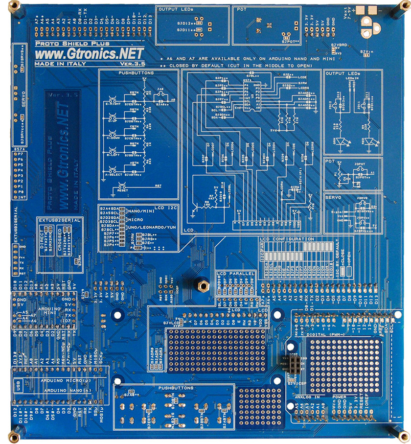
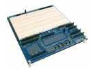
Proto Shield Plus BOTTOM side
The bottom side of the Proto Shield Plus board comes with detailed silkscreen describing all connections and jumper settings.

Using the Proto Shield Plus with Arduino UNO, LEONARDO, YÚN, NANO and MICRO
Read more
Published : 16/03/2018 09:15:13
Using the Proto Shield Plus with Arduino MINI
Read more
Published : 21/03/2018 22:38:23