Nessun prodotto
BLOG NEWS
 USARE UN DISPLAY LCD 16x2 CON LA IOT PROTO SHIELD PLUS
  Cosa ne pensa Paolo Aliverti della IoT Proto Shield Plus?
  USARE UN DISPLAY OLED SSD1306 128X64 CON LA IOT PROTO SHIELD PLUS
  USARE UN DISPLAY OLED SSD1306 128x64 CON LA IoT PROTO SHIELD PLUS
  Il Bus I2C sulla IoT Proto Shield Plus
 Search on blog
Follow us on facebook
I più venduti
-

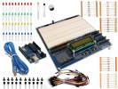
Proto Shield Plus STARTER KIT
Questo kit è rivolto principalmente a chi desidera iniziare a...
69,90 € -

Proto Shield Plus LCD KIT
La scheda PROTO SHIELD PLUS rende comodo ed immediato sperimentare e...
56,00 € -

Adattatore da SMD a piastra sperimentale (confezione 10pz)
Adatta facilmente componenti SMD a piastra sperimentale (breadboard) con...
3,90 € -

Proto Shield Plus KIT BASE
La scheda PROTOSHIELD PLUS rende comodo ed immediato sperimentare e...
52,00 €
Using an LCD display with the Proto Shield Plus - I2C configuration
Published : 29/03/2018 11:09:30
Categories : Proto Shield Plus
USING AN LCD DISPLAY WITH THE PROTO SHIELD PLUS - I2C CONFIGURATION
Having a “plug and play” LCD display could be very useful for:
- debug your code while prototyping
- create a preliminary interface to display your data while prototyping
- create the final interface for your project
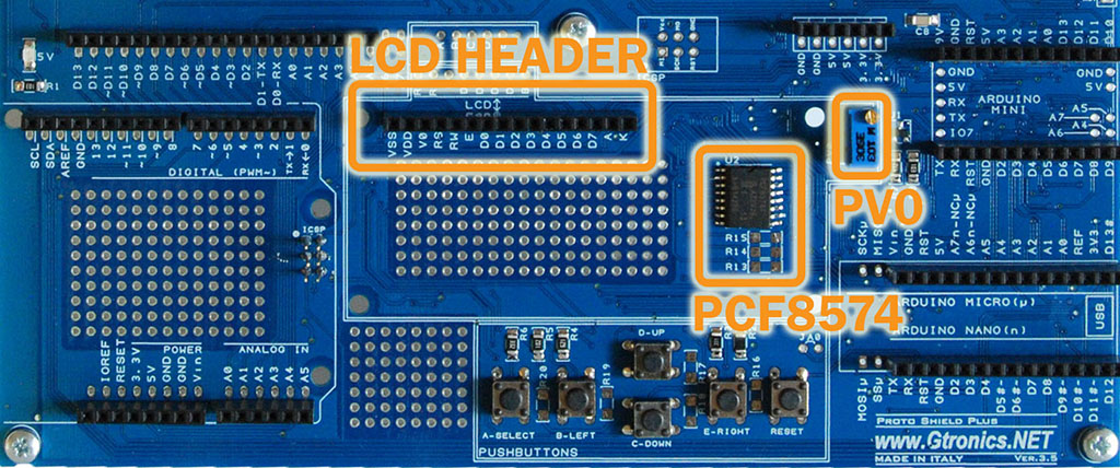
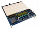
The LCD header provided on the Proto Shield Plus is designed to directly plug a standard 16pin 1602 LCD Module.
The LCD works with I2C communication (by default) or parallel configuration (jumper selectable).
PV0 adjusts the LCD contrast (all the Proto Shield Plus boards are tested one by one and the PV0 is adjusted to get a good contrast, however it can slightly differ depending on your 1602 LCD module, if you have a base Kit or you change the display you may have to adjust it).
R7, R8 and U1 drive the LCD backlight.
The on-board PCF8574 (I2C I/O expander) drives the LCD by default.
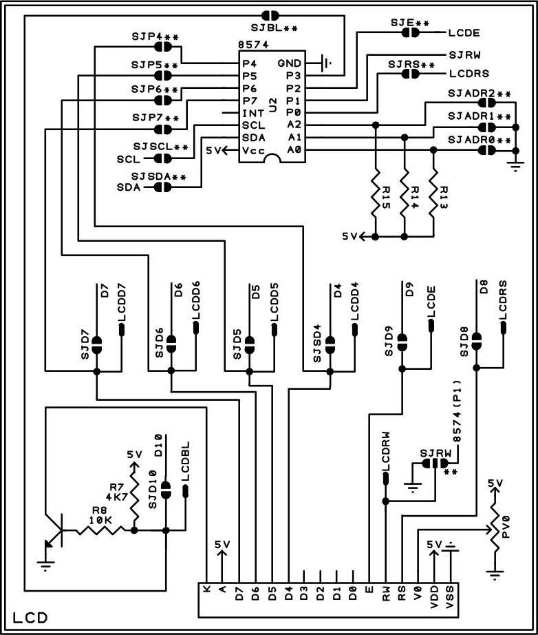
LCD connection schematic (**SJ jumpers are closed by default)
USING THE LCD Display with I2C CONFIGURATION
Since I2C configuration is the default configuration, connecting a LCD 1602 does not require any additional wiring.
Signal connections are the same used in the LCD I2C adapter of wide spread use.
It is required to download and install the LiquidCrystal_I2C library to use the Proto Shield Plus with this configuration.
Refer to the sketch APSP_demo_I2C in the APSP_Sample_Projects_V3.zip (Click here to download) file.
Depending on component availability, the I/O expander 8574 could be the PCF8574 or the PCF8574A.
Both versions perform the same, the only difference is the base address of the I2C communication.
Since A0, A1 and A2 of the PCF8574 connect to ground by default (by means of SJADR0, SJADR1 and SJADR2), the default address is set to 0x20 (PCF8574) or 0x38 (PCF8574A).
In order to help you to quickly find the address of your board do as follow:
- download the APSP_demo_I2C (APSP_Sample_Projects_V3.zip, click here to download ) sketch to your Arduino
- plug it into the Proto Shield Plus
- power the Arduino up
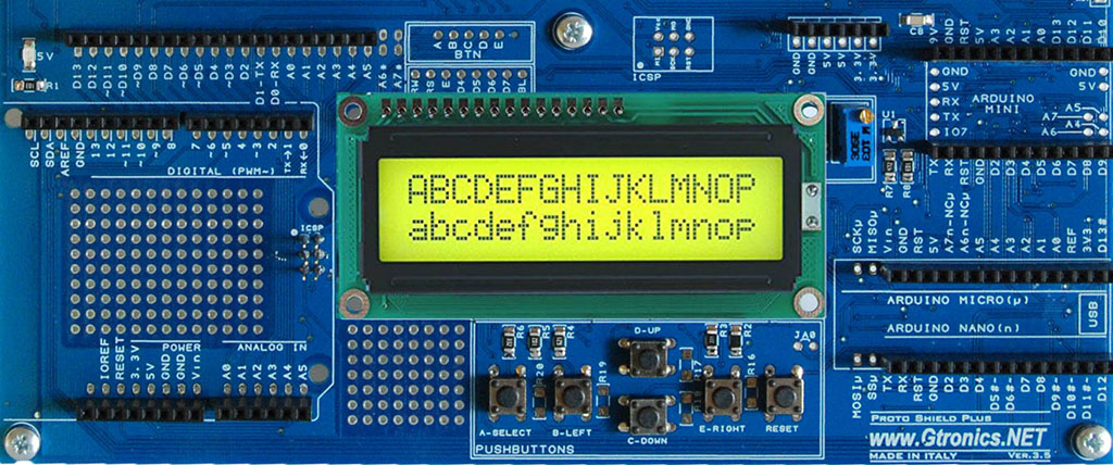
- the LCD display will show you the current address regardless of the address itself
Otherwise use the I2C_scanner sketch from the APSP_Sample_Projects_V3.zip (click here to download) file.
CONFIGURING SCL AND SDA TO WORK WITH DIFFERENT ARDUINO BOARDS
SCL and SDA (the pins that perform the I2C communication) pinout is different depending on the Arduino board.
Thus, you have to select the proper configuration depending on the board you are using.
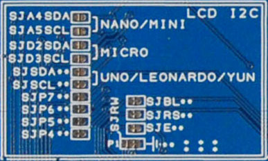
Use SJSCL, SJSDA, SJD3SCL, SJD2SDA, SJA5SCL and SJA4SDA jumpers to configure the I2C connection.
Following are the different configurations.
When using the Proto Shield Plus in I2C configuration, SJD4, SJD5, SJD6, SJD7, SJD8, SJD9 and SJD10 must be OPEN (default configuration).
Jumpers used to select the I2C LCD configuration
USING I2C CONFIGURATION WITH UNO / LEONARDO / YÚN BOARDS
Default configuration
SJA4SDA = OPEN
SJA5SCL = OPEN
SJD2SDA = OPEN
SJD3SCL = OPEN
SJSDA = CLOSE
SJSCL = CLOSE
Using I2C configuration with MICRO boards
SJA4SDA = OPEN
SJA5SCL = OPEN
SJD2SDA = CLOSE
SJD3SCL = CLOSE
SJSDA = OPEN
SJSCL = OPEN
Since SJSDA and SJSCL are closed by default, cut in the middle to open them.
USING I2C CONFIGURATION WITH NANO / MINI BOARDS
SJA4SDA = OPEN
SJA5SCL = OPEN
SJD2SDA = CLOSE
SJD3SCL = CLOSE
SJSDA = OPEN
SJSCL = OPEN
Since SJSDA and SJSCL are closed by default, cut in the middle to open them.
On the MINI board, SCL and SDA signals are mapped on A5 and A4, therefore you must connect these two pins of the MINI to the Proto Shield Plus if you want to use the MINI board with I2C connection.
Changing the address of the I2C communication
It is not very usual but in case that you want / need to change the address of the 8574 chip, you have to install R13, R14 and R15 Pull-up resistors.
Refer to the PCF8574 datasheet to configure the base address, open or close SJADR0, SJADR1 and SJADR2 (cut in the middle to open them) in order to fit your needs.
In the next article we will see how to use the Proto Shield Plus with LCD parallel configuration.
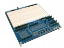

The Proto Shield Plus Board Layout
Read more
Published : 09/03/2018 10:45:38
Using an LCD display with the Proto Shield Plus - Parallel configuration
Read more
Published : 06/04/2018 11:11:23