No products
BLOG NEWS
 USING A 16x2 LCD DISPLAY WITH THE IoT PROTO SHIELD PLUS
  What does Paolo Aliverti say about the IoT Proto Shield Plus?
  USING AN SSD1306 128x32 OLED DISPLAY (I2C type) WITH THE IoT PROTO SHIELD PLUS
  USING AN SSD1306 128x64 OLED DISPLAY (I2C type) WITH THE IoT PROTO SHIELD PLUS
  I2C Bus on the IoT Proto Shield Plus
 Search on blog
Follow us on facebook
Top sellers
-

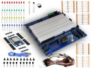
Proto Shield Plus STARTER KIT
This kit is the ideal solution for those who want to start to prototype...
69,90 € -

Proto Shield Plus LCD KIT
Prototype with ARDUINO / GENUINO boards without having a lot of wires...
56,00 € -

SMD to breadboard adapter (10 pcs pack)
Easily adapt SMD devices to 2.54mm prototyping breadboards.
3,90 € -

Proto Shield Plus BASE KIT
Prototype with ARDUINO / GENUINO boards without having a lot of wires...
52,00 €
I2C Bus on the IoT Proto Shield Plus
Published : 04/22/2022 09:41:11
Categories : IoT Proto Shield Plus , Proto Shield Plus
I2C BUS on the IoT Proto Shield Plus
I2C (Inter-Integrated Circuit, eye-squared-C) is widely used for attaching peripheral ICs to processors and microcontrollers (check out more about I2C Wikipedia or other online documentation).
I2C on the IoT Proto Shield Plus is used to communicate with devices such as displays, RTC clock, etc.
I2C signals routing on the IoT Proto Shield Plus
DEFAULT CONNECTIONS
I2C signals on the IoT Proto Shield Plus are routed by default according to the following connections:
SCANNING FOR I2C DEVICES
You can use the sample sketch IoTPSP_I2C_scanner (location: IoTPSP_Sample_SketchesIoTPSP_I2C_scanner) to scan the I2C bus.
The scanner shows connected I2C devices addresses. With no external devices (such as OLED displays etc.) the scanner shows the address of the PCF8574 onboard chip (usually 0x20 or 0x38).
Using the I2C with different GPIO pins
Most of the libraries used to communicate to I2C devices, use the default I2C GPIO pins (see default connections here), thus it is NOT recommended to reroute I2C signals.
Anyway, if you want or need, follow the instructions below.
According to the above figure, I2C signals are routed to the default GPIO pins by means of JP6 and JP7.
To disconnect I2C signals from their default GPIO pins, you must OPEN JP6 and JP7 pads 1-2 (cut in the middle of pad 1 and pad 2) and CLOSE pads 2 with pad 3 (by means of a little drop of tin).
Solder a header on J41 and, by means of some jumper wires, connect other GPIO pins according to your needs.
Please check the default signal routing of the IoT Proto Shield Plus (see default connections here) to avoid conflict with other default connections.
Related products
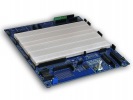
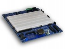

Introducing the new IoT Proto Shield Plus
Read more
Published : 11/11/2021 08:34:28
5V and 3V3 on the IoT Proto Shield Plus board
Read more
Published : 02/04/2022 08:40:16
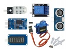
Plug & Play modules on the IoT Proto Shield Plus
Read more
Published : 01/13/2022 15:43:02
The IoT Proto Shield Plus Layout
Read more
Published : 12/17/2021 09:12:04
Using the IoT Proto Shield Plus with Arduino and ESP boards
Read more
Published : 02/11/2022 08:36:34