No products
BLOG NEWS
 USING A 16x2 LCD DISPLAY WITH THE IoT PROTO SHIELD PLUS
  What does Paolo Aliverti say about the IoT Proto Shield Plus?
  USING AN SSD1306 128x32 OLED DISPLAY (I2C type) WITH THE IoT PROTO SHIELD PLUS
  USING AN SSD1306 128x64 OLED DISPLAY (I2C type) WITH THE IoT PROTO SHIELD PLUS
  I2C Bus on the IoT Proto Shield Plus
 Search on blog
Follow us on facebook
Top sellers
-

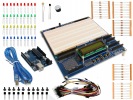
Proto Shield Plus STARTER KIT
This kit is the ideal solution for those who want to start to prototype...
69,90 € -

Proto Shield Plus LCD KIT
Prototype with ARDUINO / GENUINO boards without having a lot of wires...
56,00 € -

SMD to breadboard adapter (10 pcs pack)
Easily adapt SMD devices to 2.54mm prototyping breadboards.
3,90 € -

Proto Shield Plus BASE KIT
Prototype with ARDUINO / GENUINO boards without having a lot of wires...
52,00 €
Using Arduino ZERO with the Proto Shield Plus
Published : 07/25/2018 11:41:25
Categories : Proto Shield Plus
Using Arduino ZERO with the Proto Shield Plus
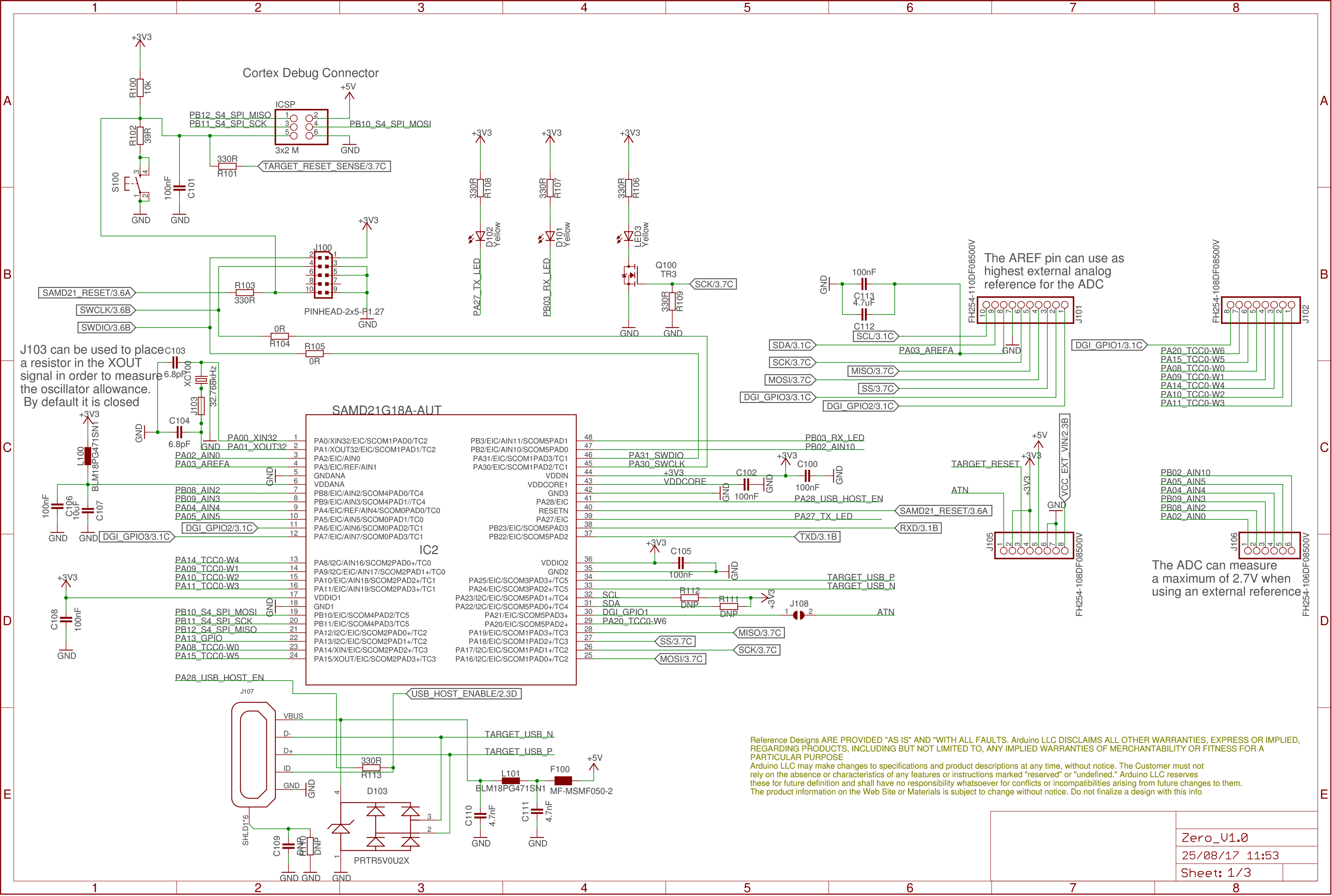
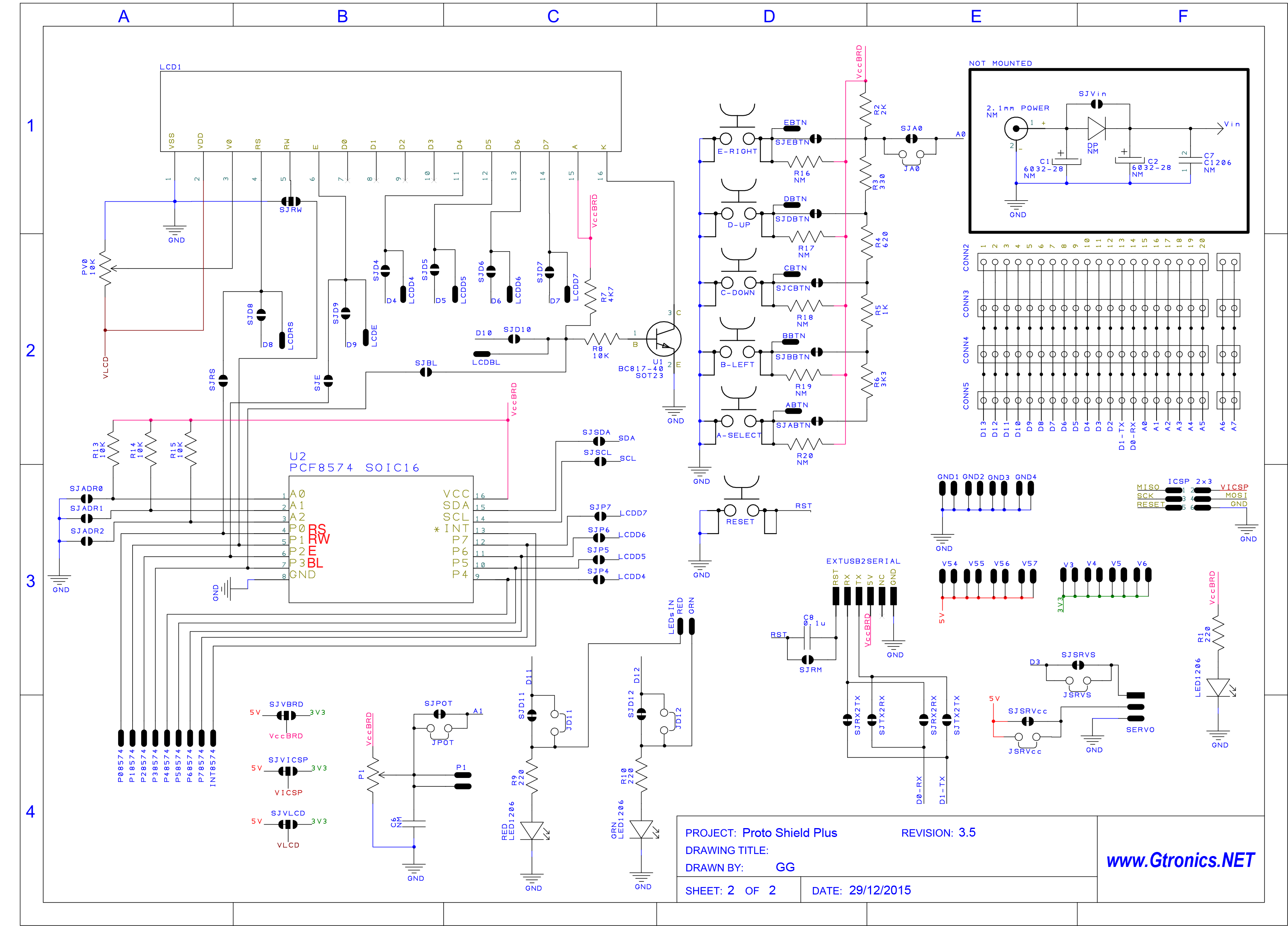
Arduino ZERO is a powerful 32-bit board based on the ATSAMD21G18, 32-Bit ARM Cortex M0+ MCU.
It runs at 48Mhz, so, if you need speed and power for your application this board may fit your needs.
The biggest problem with this "new" generation of Arduino boards is related to their operating voltage which is 3,3V unlike the "standard" 5V.
The Arduino.cc website warns you:
Warning: Unlike most Arduino & Genuino boards, the Zero runs at 3.3V. The maximum voltage that the I/O pins can tolerate is 3.3V. Applying voltages higher than 3.3V to any I/O pin could damage the board.
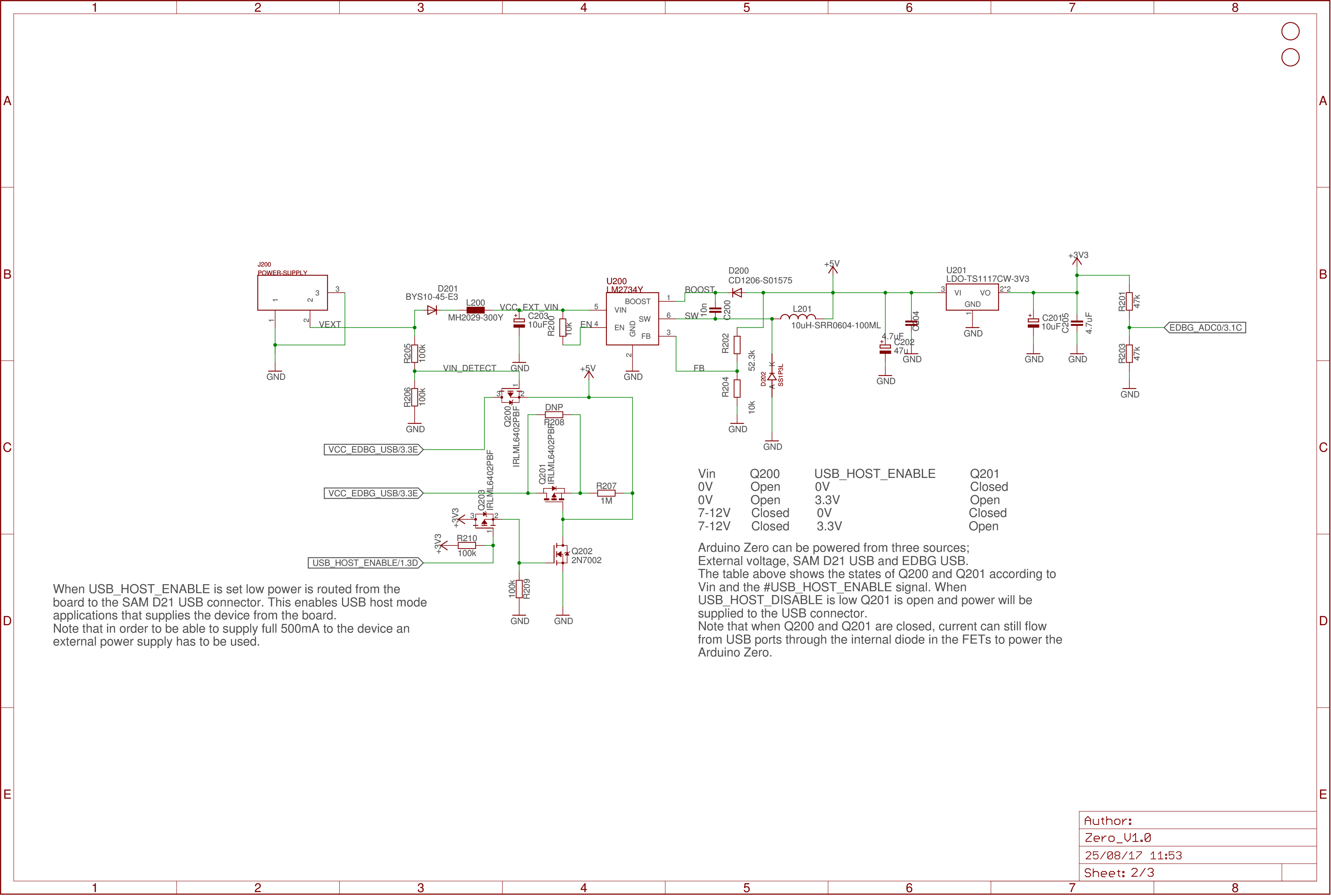
Anyway 5V will be present due to the external USB 5V power supply or the on-board LM2734Y (U200), in case that you are powering the board with an external power supply.
Switching the Proto Shield Plus board voltage from 5V to 3V3
Locate SJVBRD on the bottom of the Proto Shield Plus.
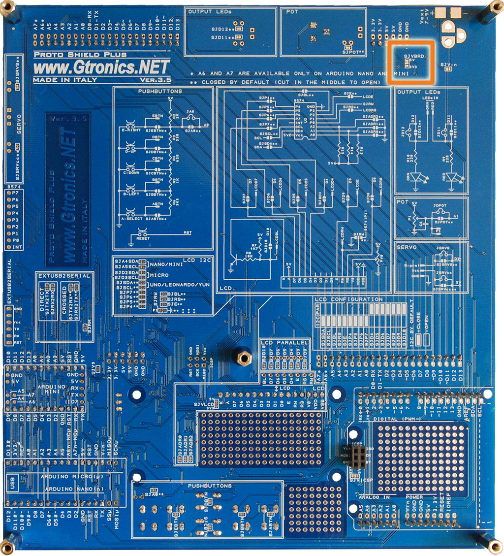
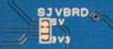
As you can see from the image above, the Proto Shield Plus comes with 5V by default as "board" voltage, which means that VccBRD is 5V (see Proto Shield Plus schematics for details).
With a sharp blade (i.e. a cutter) cut between the central pad and the 5V pad.
With soldering iron and a little drop of tin, short between the central pad and the 3V3 pad.
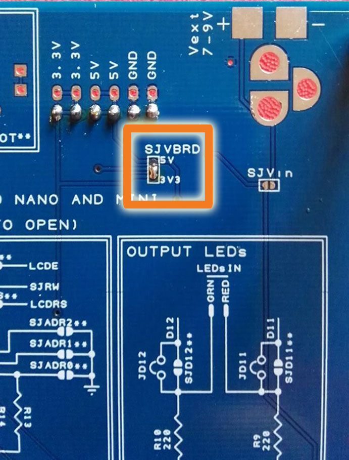
Now the board voltage of your Proto Shield Plus is 3V3, which means that POT and pushbuttons connect to 3V3 instead of 5V.
Using the on-board I2C PCF8254 to drive LCD or to expand I/O
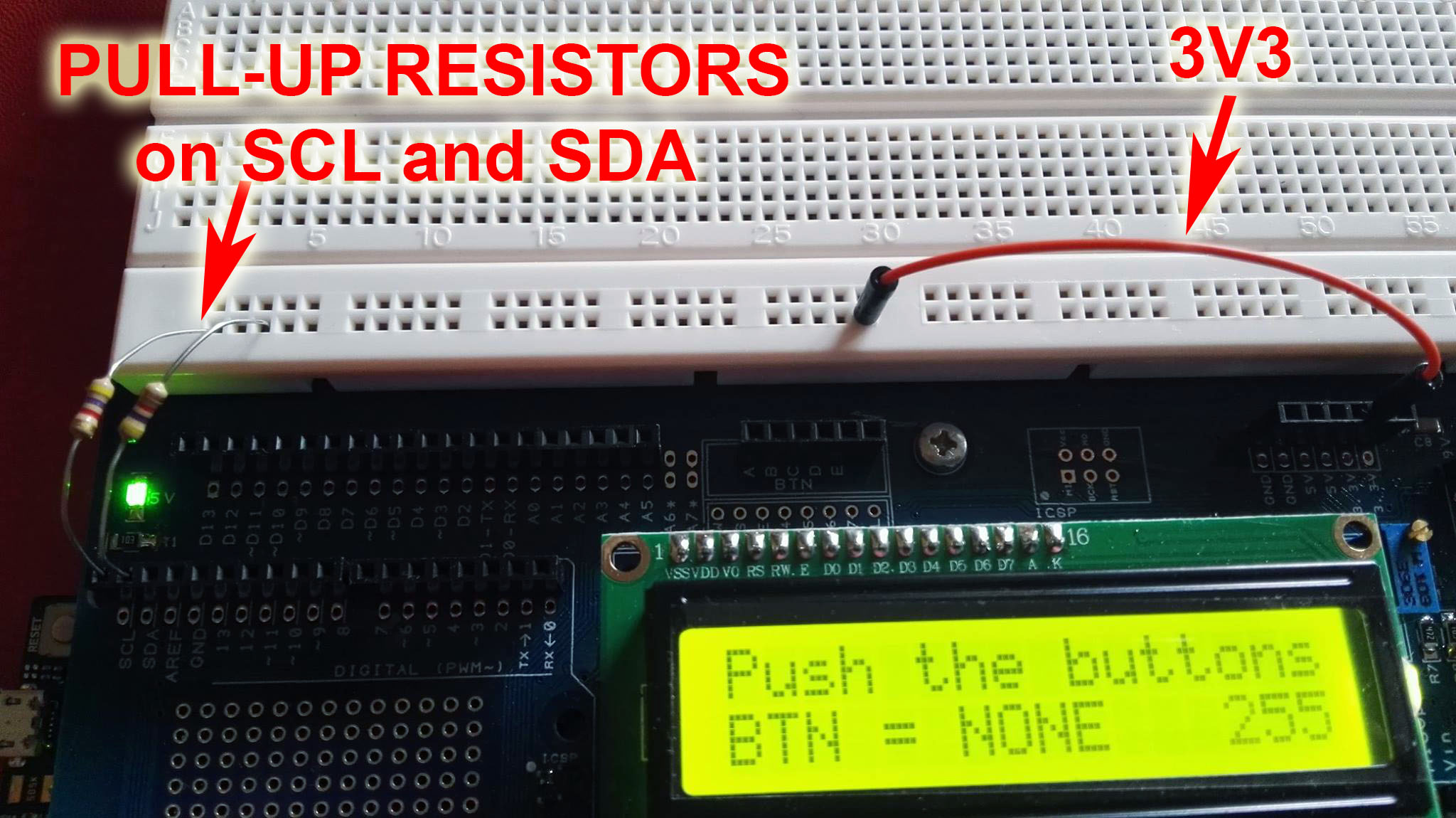
Not all the Arduino users know that SCL and SDA need pull-up resistors to let the I2C communication work properly (see Wire Library documentation, click here)
[...] Please note that a pull-up resistor is needed when connecting SDA/SCL pins. [...]
Anyway the Wire Library activates internal pull-up resistor for you, so with other boards (like UNO, NANO, MINI etc.) you do not have to add any hardware to let the I2C works.
This is not the case of the ZERO board, which requires two additional external pull-up resistors.
In the image below two 4K7 ohm resistors connect SCL and SDA pins to 3V3.
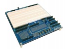

The Proto Shield Plus Board Layout
Read more
Published : 03/09/2018 10:45:38
The PCF8574 I2C I/O expander of the Proto Shield Plus
Read more
Published : 06/27/2018 09:41:27
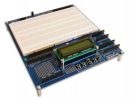
Using an LCD display with the Proto Shield Plus - I2C configuration
Read more
Published : 03/29/2018 11:09:30
Using the Proto Shield Plus with Arduino UNO, LEONARDO, YÚN, NANO and MICRO
Read more
Published : 03/16/2018 09:15:13