No products
BLOG NEWS
 USING A 16x2 LCD DISPLAY WITH THE IoT PROTO SHIELD PLUS
  What does Paolo Aliverti say about the IoT Proto Shield Plus?
  USING AN SSD1306 128x32 OLED DISPLAY (I2C type) WITH THE IoT PROTO SHIELD PLUS
  USING AN SSD1306 128x64 OLED DISPLAY (I2C type) WITH THE IoT PROTO SHIELD PLUS
  I2C Bus on the IoT Proto Shield Plus
 Search on blog
Follow us on facebook
Top sellers
-

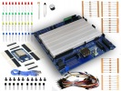
Proto Shield Plus STARTER KIT
This kit is the ideal solution for those who want to start to prototype...
69,90 € -

Proto Shield Plus LCD KIT
Prototype with ARDUINO / GENUINO boards without having a lot of wires...
56,00 € -

SMD to breadboard adapter (10 pcs pack)
Easily adapt SMD devices to 2.54mm prototyping breadboards.
3,90 € -

Proto Shield Plus BASE KIT
Prototype with ARDUINO / GENUINO boards without having a lot of wires...
52,00 €
The Onboard Encoder of the IoT Proto Shield Plus
Published : 03/18/2022 09:55:54
Categories : IoT Proto Shield Plus , Proto Shield Plus
The on-board ENCODER of the IoT Proto Shield Plus
The IoT Proto Shield Plus comes with one on-board rotary ENCODER, it is useful to quickly setup your prototyping environment.
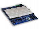
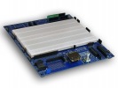
ENCODER Section of the IoT Proto Shield Plus 

Schematic of the IoT Proto Shield Plus ENCODER Section 
Default connections

Please note that there are no default connections for the ESP8266. If you need to use the ENCODER with ESP8266 boards, you need to route the signals with jumper wires.
Suggested ESP8266 connections
The sample sketches are made to work with these connections:
ESP8622 GPIO 14 (D5) connected to header J3 ESP32 GPIO33 (ENC_SW)
ESP8622 GPIO 5 (D1) connected to header J3 ESP32 GPIO27 (ENC_A)
ESP8622 GPIO 4 (D2) connected to header J3 ESP32 GPIO35 (ENC_B)

Sample Sketches
The sample sketches are very easy, they let you track and read the ENCODER position.
Download the sample sketches by clicking here.
Location: IoTPSP_Sample_Sketches/IoTPSP_ENC
Open the serial monitor and rotate the encoder knob to see its incremental position changing or press the encoder knob to see the GRN led changing its status.
Use the IoTPSP_ENCODER_Simple_NANO sketch to test the ENCODER with ARDUINO NANO boards.
Use the IoTPSP_ENCODER_Simple_ESP32 sketch to test the ENCODER with ESP32 boards.
Use the IoTPSP_ENCODER_Simple_ESP8266 sketch to test the ENCODER with ESP8266 boards.
A more robust way to manage the A and B signals of the ENCODER is using the interrupts.
Use the IoTPSP_ENCODER_Interrupt_NANO sketch to test the ENCODER with ARDUINO NANO boards using interrupts.
Use the IoTPSP_ENCODER_Interrupt_ESP32 sketch to test the ENCODER with ESP32 boards using interrupts.
Use the IoTPSP_ENCODER_Interrupt_ESP8266 sketch to test the ENCODER with ESP8266 boards using interrupts.
Using the ENCODER with different GPIO pins
According to the above schematics, ENCODER signals are routed to the default GPIO pins by means of JP18, JP19 and JP20.
To disconnect ENCODER signals from their default GPIO pins, you must open JP 18, JP19 and JP20 (cut them in the middle).
Solder a header on J9 and, by means of some jumper wires, connect other GPIO pins according to your needs.
Please check the default signal routing of the IoT Proto Shield Plus to avoid conflict with other default connections.
Related products

Introducing the new IoT Proto Shield Plus
Read more
Published : 11/11/2021 08:34:28
5V and 3V3 on the IoT Proto Shield Plus board
Read more
Published : 02/04/2022 08:40:16
The IoT Proto Shield Plus Layout
Read more
Published : 12/17/2021 09:12:04
Using the IoT Proto Shield Plus with Arduino and ESP boards
Read more
Published : 02/11/2022 08:36:34
The onboard Potentiometer of the IoT Proto Shield Plus
Read more
Published : 03/11/2022 08:37:07
Working with the onboard LEDs of the IoT Proto Shield Plus
Read more
Published : 02/25/2022 08:14:32